


Back
Global site
10" inline duct fan w/metal housing, 120V, 1~
Item #: 40014
This mixed-flow series inline duct fan combines the high airflow of axial fans with the high static pressure characteristics of backward curved impellers. This inline fan is an excellent choice for exhaust or supply applications where high static pressures need to be overcome.
• Mixed-flow impeller enabling high static pressure
The housing is manufactured from galvanized steel for corrosion resistance. The fan uses external rotor motors with a mixed flow impeller that reduces the external dimensions of the fans. General application examples include offices & commercial bathrooms, hospitals, beauty salons, veterinary clinics, and residential applications such as kitchen range hood exhausts.

| Nominal data | ||
|---|---|---|
| Voltage (nominal) | 115 | V |
| Frequency | 60 | Hz |
| Phases | 1~ | |
| Input power | 305 | W |
| Input current | 3.01 | A |
| Impeller speed | 2,699 | rpm |
| Air flow | max 909 | cfm |
| Temperature of transported air | max 140 | °F |
| Max temperature of transported air, when speed controlled | 140 | °F |
| Protection/Classification | ||
|---|---|---|
| Enclosure class, motor | IP44 | |
| Insulation class | B | |
| Certificate | AMCA Air, AMCA Sound, cULus |
| Dimensions and weights | ||
|---|---|---|
| Duct dimension; Circular, inlet | 10 | in. |
| Duct dimension; Circular, inlet | 10 | in. |
| Duct dimension; Circular, outlet | 10 | in. |
| Weight | 14.3 | lb |
| Optional | ||
|---|---|---|
| Duct connection type | Circular | |
| Motor type | AC | |
| Material | Metal |
| CFM Table | ||||||||
Model |
0" Ps |
0.2" Ps |
0.4" Ps |
0.6" Ps |
0.8" Ps |
1.0" Ps |
1.5" Ps |
2.0" Ps |
8XL |
836 |
778 |
712 |
645 |
578 |
499 |
286 |
- |
10 |
910 |
848 |
785 |
715 |
630 |
547 |
342 |
- |
10XL |
1266 |
1203 |
1135 |
1056 |
980 |
900 |
696 |
460 |
12 |
1305 |
1245 |
1182 |
1110 |
1030 |
948 |
712 |
479 |
12XL |
2016 |
1865 |
1720 |
1568 |
1385 |
1066 |
104 |
- |
14 |
2156 |
2010 |
1845 |
1665 |
1460 |
1193 |
145 |
- |
14XL |
2619 |
2470 |
2285 |
2095 |
1895 |
1662 |
843 |
- |
16 |
2952 |
2758 |
2565 |
2325 |
2085 |
1804 |
774 |
- |
16XL |
4274 |
4090 |
3900 |
3655 |
3317 |
3137 |
2379 |
1242 |
18 |
4448 |
4213 |
3984 |
3736 |
3488 |
3239 |
2380 |
1231 |
18XL |
6212 |
5960 |
5735 |
5560 |
5354 |
5163 |
4608 |
3704 |
20 |
6271 |
6107 |
5965 |
5800 |
5595 |
5396 |
4813 |
3792 |
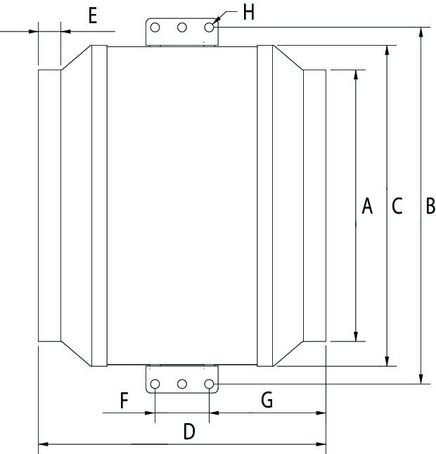
| Model | A | B | C | D | E | F | G | H |
8XL |
8 (203) |
14 (356) |
12 1/2 (318) |
15 1/2 (394) |
3/4 (19) |
2 3/8 (60) |
6 1/8 (156) |
3/8 (10) |
10 |
10 (254) |
14 (356) |
12 1/2 (318) |
12 1/2 (318) |
3/4 (19) |
2 3/8 (60) |
5 (127) |
3/8 (10) |
10XL |
10 (254) |
15 5/8 (397) |
14 (356) |
15 (381) |
3/4 (19) |
2 3/8 (60) |
6 3/8 (162) |
3/8 (10) |
12 |
12 (305) |
15 5/8 (397) |
14 (356) |
12 1/2 (318) |
3/4 (19) |
2 3/8 (60) |
5 1/8 (130) |
3/8 (10) |
Dimensions in inches (mm) |
||||||||
GUIDE SPECIFICATION
Specifier Notes: This guide specification is written in Construction Specifications Institute (CSI) 3-Part Format in accordance with the CSI Construction Specifications Practice Guide, MasterFormat, SectionFormat, and PageFormat.
Specifier Notes: This Section must be carefully reviewed and edited by the Architect or Engineer to meet the requirements of the Project and local building code. Coordinate this Section with Division 01, other specification sections, and the Drawings. Delete all Specifier Notes after editing this Section.
Section numbers and titles are based on MasterFormat 2014 Update.
SECTION 23 34 16
CENTRIFUGAL HVAC FANS
Specifier Notes: This Section covers Fantech FKD/KD Series circular inline duct fans with alternating current (AC) motors. Consult Fantech for assistance in editing this Section as required for the Project.
PART 1. GENERAL
1.1 SECTION INCLUDES
A. Circular inline duct fans with alternating current (AC) motors
1.2 RELATED REQUIREMENTS
Specifier Notes: Edit the following list of related sections as required for the Project. Limit the list to sections with specific information that the reader might expect to find in this Section but is specified elsewhere.
A. Section 23 31 00 – HVAC Ducts and Casings.
B. Section 26 05 00 – Common Work Results for Electrical.
1.3 REFERENCE STANDARDS
Specifier Notes: List reference standards used elsewhere in this Section, complete with designations and titles. Delete reference standards from the following list not used in the edited Section.
A. Air Movement and Control Association International (AMCA) (www.amca.org):
1. AMCA 211 – Certified Ratings Program - Product Rating Manual for Fan Air Performance.
2. AMCA 311 – Certified Sound Ratings Program for Air Moving Devices.
B. Underwriting Laboratory (UL) (https://productiq.ulprospector.com/en):
1. UL 507— Electric Fans
2. CSA 22.2 No 113 — Fans and Ventilators
1.4 PREINSTALLATION MEETINGS
Specifier Notes: Edit the Preinstallation Meetings article as required for the Project. Delete article if not required.
A. Convene preinstallation meeting [1 week] [2 weeks] before start of Work of this Section.
B. Require attendance of parties directly affecting Work of this Section, including Contractor, Architect, installer, and manufacturer’s representative.
C. Review the Following:
1. Materials
2. Installation
3. Adjusting
4. Protection
5. Coordination with other Work
1.5 SUBMITTALS
Specifier Notes: Edit the Submittals article as required for the Project. Delete submittals not required.
A. Comply with Division 01.
B. Product Data: Submit manufacturer’s product data, including installation instructions.
C. Shop Drawings: Submit manufacturer’s shop drawings, including plans, elevations, sections, and details.
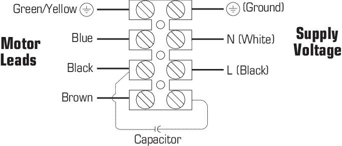
1. Wiring Diagrams: Indicate wiring for each item of equipment and interconnections between items of equipment.
2. Include manufacturer’s names, model numbers, ratings, power requirements, equipment layout, device arrangement, complete wiring point-to-point diagrams, and conduit layouts.
D. Manufacturer’s Certification: Submit manufacturer’s certification that materials comply with specified requirements and are suitable for intended application.
E. Operation and Maintenance Data:
1. Submit manufacturer’s operation and maintenance manual; including the following:
a. Operation, maintenance, adjustment, and cleaning instructions.
b. Troubleshooting guide
c. Parts list
d. Electrical wiring diagrams if required.
2. Provide detailed information required for Owner to properly operate and maintain equipment.
F. Warranty Documentation: Submit manufacturer’s standard warranty.
1.6 QUALITY ASSURANCE
A. Manufacturer’s Qualifications: Manufacturer regularly engaged in the manufacturing of circular inline duct fans to that specified for a minimum of 10 years.
B. Installer's Qualifications:
1. Installer regularly engaged in installation of circular inline duct fans of similar type to that specified for a minimum of 5 years.
2. Use persons trained for installation of circular inline duct fans.
1.7 DELIVERY, STORAGE, AND HANDLING
A. Delivery Requirements: Deliver materials to site in manufacturer’s original, unopened containers and packaging, with labels clearly identifying product name and manufacturer.
B. Storage and Handling Requirements:
1. Store and handle materials in accordance with manufacturer’s instructions.
2. Keep materials in manufacturer’s original, unopened containers and packaging until installation.
3. Store materials in clean, dry area indoors.
4. Keep materials from freezing.
5. Protect materials during storage, handling, and installation to prevent damage.
1.8 LIMITED FACTORY WARRANTY
Warranty Period: 5 years
PART 2. PRODUCTS
2.1 MANUFACTURERS
A. Manufacturer: Systemair MFG Inc., 10048 Industrial Blvd., Lenexa, Kansas 66215. Phone 800-747-6217. www.fantech.net. ussupport@fantech.net.
Specifier Notes: Specify if substitutions will be permitted.
B. Substitutions: [Not permitted] [Comply with Division 01].
C. Single Source: Provide materials from single manufacturer.
2.2 CENTRIFUGAL HVAC FANS
A. Supply, exhaust, or return air inline fans shall be of the centrifugal direct-driven type: FKD/KD Series
1. Fan airflow rating in accordance with ANSI/AMCA 210
2. Fan sound rating in accordance with ANSI/AMCA 300
3. AMCA Air & Sound Seal
4. UL Listed 507 Electric Fans
5. CSA 22.2 No 113 — Fans and Ventilators
B. Housing
1. Fan housing shall be constructed of heavy gauge galvanized sheet metal
2. Fan shall be supplied with externally mounted electrical terminal box with pre-wired terminal strip connections
C. Motor
1. Single phase motors (FKD 8XL–FKD 12 /KD 8XL-KD 12) shall be 120 or 230V permanent split capacitor type
2. All motors shall be a permanently sealed self lubricating ball bearing type
3. Single phase motors shall be equipped with automatic reset thermal overload protection
4. Motors shall be acceptable for continuous duty
5. Sufficient service factor shall be provided to ensure long maintenance free operation over maximum load conditions
D. Wheel
1. Fan wheel shall be of the mixed flow centrifugal type with a well designed inlet venturi for maximum performance
2. Motorized impeller shall be both statically and dynamically balanced as one integral unit to provide for vibration free performance
3. The material of the motor impellers for the FKD 8XL–FKD 12 and KD 8XL-KD 12 shall be constructed of aluminum
Specifier Notes: Specify circular inline duct fan models as required for the Project; delete models not required.
E. Model: “FKD 8XL/KD 8XL”
1. Inlet Diameter: 8 inches (203mm)
2. Outlet Diameter: 8 inches (203mm)
3. Casing Diameter: 12-1/2 inches (318 mm)
4. Inlet and Outlet Connection Collars: 3/4 inch (19mm)
5. Casing Material: Galvanized Sheet Metal
6. Motor: Alternating current external-rotor motor
7. Speed Control: By altering supply voltage via an external stepless controller
8. Motor Protection: Thermal overload protection
9. Blades: Backward curved
10. Voltage: 115 V
11. Frequency: 60 Hz
12. Nominal Voltage Range: 100 to 130 V
13. Phase: 1
14. Maximum Airflow: 837 cfm
15. Impeller Speed: 2,599 rpm
16. Power Rating, Motor: 318 W
17. Input Current: 2.99 A
18. Operational Temperature: -13 to 140 degrees F (-25 to 60 degrees C)
19. Weight: 14.8 lbs (6.7kg)
20. Motor Insulation Class: B
21. Motor Enclosure Class: IP44
F. Model: “FKD 8XL 230 V”
1. Inlet Diameter: 8 inches (203mm)
2. Outlet Diameter: 8 inches (203mm)
3. Casing Diameter: 12-1/2 inches (318 mm)
4. Inlet and Outlet Connection Collars: 3/4 inch (19mm)
5. Casing Material: Galvanized Sheet Metal
6. Motor: Alternating current external-rotor motor
7. Speed Control: By altering supply voltage via an external stepless controller
8. Motor Protection: Thermal overload protection
9. Blades: Backward curved
10. Voltage: 230 V
11. Frequency: 60 Hz
12. Nominal Voltage Range: 208 to 240 V
13. Phase: 1
14. Maximum Airflow: 820 cfm
15. Impeller Speed: 2,695 rpm
16. Power Rating, Motor: 319 W
17. Input Current: 1.5 A
18. Operational Temperature: -13 to 122 degrees F (-25 to 50 degrees C)
19. Weight: 14.9 lbs (6.8kg)
20. Motor Insulation Class: B
21. Motor Enclosure Class: IP54
G. Model: “FKD 10/KD 10”
1. Inlet Diameter: 10 inches (254mm)
2. Outlet Diameter: 10 inches (254mm)
3. Casing Diameter: 14 inches (356 mm)
4. Inlet and Outlet Connection Collars: 3/4 inch (19mm)
5. Casing Material: Galvanized Sheet Metal
6. Motor: Alternating current external-rotor motor
7. Speed Control: By altering supply voltage via an external stepless controller
8. Motor Protection: Thermal overload protection
9. Blades: Backward curved
10. Voltage: 115 V
11. Frequency: 60 Hz
12. Nominal Voltage Range: 100 to 130 V
13. Phase: 1
14. Maximum Airflow: 909 cfm
15. Impeller Speed: 2,699 rpm
16. Power Rating, Motor: 305 W
17. Input Current: 3.01 A
18. Operational Temperature: -13 to 140 degrees F (-25 to 60 degrees C)
19. Weight: 14.3 lbs (6.5kg)
20. Motor Insulation Class: B
21. Motor Enclosure Class: IP44
H. Model: “FKD 10XL/KD 10XL”
1. Inlet Diameter: 10 inches (254mm)
2. Outlet Diameter: 10 inches (254mm)
3. Casing Diameter: 14 inches (356 mm)
4. Inlet and Outlet Connection Collars: 3/4 inch (19mm)
5. Casing Material: Galvanized Sheet Metal
6. Motor: Alternating current external-rotor motor
7. Speed Control: By altering supply voltage via an external stepless controller
8. Motor Protection: Thermal overload protection
9. Blades: Backward curved
10. Voltage: 115 V
11. Frequency: 60 Hz
12. Nominal Voltage Range: 100 to 130 V
13. Phase: 1
14. Maximum Airflow: 1,267 cfm
15. Impeller Speed: 2,889 rpm
16. Power Rating, Motor: 485 W
17. Input Current: 4.84 A
18. Operational Temperature: -13 to 140 degrees F (-25 to 60 degrees C)
19. Weight: 20.5 lbs (9.3kg)
20. Motor Insulation Class: B
21. Motor Enclosure Class: IP44
I. Model: “FKD 10XL/KD 10XL - 230V”
1. Inlet Diameter: 10 inches (254mm)
2. Outlet Diameter: 10 inches (254mm)
3. Casing Diameter: 14 inches (356 mm)
4. Inlet and Outlet Connection Collars: 3/4 inch (19mm)
5. Casing Material: Galvanized Sheet Metal
6. Motor: Alternating current external-rotor motor
7. Speed Control: By altering supply voltage via an external stepless controller
8. Motor Protection: Thermal overload protection
9. Blades: Backward curved
10. Voltage: 230 V
11. Frequency: 60 Hz
12. Nominal Voltage Range: 208 to 240 V
13. Phase: 1
14. Maximum Airflow: 1,265 cfm
15. Impeller Speed: 2,946 rpm
16. Power Rating, Motor: 514 W
17. Input Current: 2.25 A
18. Operational Temperature: -13 to 140 degrees F (-25 to 60 degrees C)
19. Weight: 24.6 lbs (11.2kg)
20. Motor Insulation Class: F
21. Motor Enclosure Class: IP54
J. Model: “FKD 12/KD 12”
1. Inlet Diameter: 12 inches (305mm)
2. Outlet Diameter: 12 inches (305mm)
3. Casing Diameter: 14 inches (356mm)
4. Inlet and Outlet Connection Collars: 3/4 inch (19mm)
5. Casing Material: Galvanized Sheet Metal
6. Motor: Alternating current external-rotor motor
7. Speed Control: By altering supply voltage via an external stepless controller
8. Motor Protection: Thermal overload protection
9. Blades: Backward curved
10. Voltage: 115 V
11. Frequency: 60 Hz
12. Nominal Voltage Range: 100 to 130 V
13. Phase: 1
14. Maximum Airflow: 1,305 cfm
15. Impeller Speed: 2,944 rpm
16. Power Rating, Motor: 484 W
17. Input Current: 4.86 A
18. Operational Temperature: -13 to 140 degrees F (-25 to 60 degrees C)
19. Weight: 19.9 lbs (9kg)
20. Motor Insulation Class: B
21. Motor Enclosure Class: IP44
K. Model: “FKD 12/KD 12 - 230 V”
1. Inlet Diameter: 12 inches (305mm)
2. Outlet Diameter: 12 inches (305mm)
3. Casing Diameter: 14 inches (356mm)
4. Inlet and Outlet Connection Collars: 3/4 inch (19mm)
5. Casing Material: Galvanized Sheet Metal
6. Motor: Alternating current external-rotor motor
7. Speed Control: By altering supply voltage via an external stepless controller
8. Motor Protection: Thermal overload protection
9. Blades: Backward curved
10. Voltage: 230 V
11. Frequency: 60 Hz
12. Nominal Voltage Range: 208 to 240 V
13. Phase: 1
14. Maximum Airflow: 1,290 cfm
15. Impeller Speed: 2,889 rpm
16. Power Rating, Motor: 497 W
17. Input Current: 2.1 A
18. Operational Temperature: -13 to 140 degrees F (-25 to 60 degrees C)
19. Weight: 19.9 lbs (9kg)
20. Motor Insulation Class: F
21. Motor Enclosure Class: IP44
2.3 ACCESSORIES
A. Silencers for Circular Ducts
Specifier Notes: Delete accessories not required.
1. Model: [“LD 8”] [“LD 10”] [“LD 12”]
2. Insulation Thickness: 2 inches.
B. External Remotely Mounted Speed Controller
Specifier Notes: Delete if not required.
1. Model: RPE210
2. Remotely mounted manual-speed control for air flow adjustments and balancing.
3. Voltage: 230V
4. Amperage: 10A max
5. Enclosure class: IP54
C. Inlet Safety Guard
Specifier Notes: Delete if not required.
1. Model: [“IG 8”] [“IG 10”] [“IG 12”]
2. Wire ring inlet guard prevents foreign objects from entering inline duct fan Zinc chromate plated steel.
PART 3. EXECUTION
3.1 EXAMINATION
A. Examine areas to receive circular inline duct fans.
B. Notify Architect of conditions that would adversely affect installation or subsequent use.
C. Do not begin installation until unacceptable conditions are corrected.
3.2 INSTALLATION
A. Install circular inline duct fans in accordance with manufacturer’s instructions at locations indicated on the Drawings.
B. Attach duct work to inlet and outlet connection collars of circular inline duct fans in accordance with manufacturer’s instructions.
C. Electrical: Install electrical power to circular inline duct fans as specified in Section 26 05 00.
3.3 ADJUSTING
A. Adjust circular inline duct fans for proper operation in accordance with manufacturer’s instructions.
3.4 PROTECTION
A. Protect installed circular inline duct fans from damage during construction.
END OF SECTION


