


Back
Global site
Single speed, 80 CFM, 4“ Oval
Item #: 484300
With 80 CFM of airflow capability, these bathroom exhaust fans offer high quality performance with wall or ceiling mount options.
• 80 CFM (38 L/s) @ 0.1 in. wg. (25 Pa)
Our bathfan Simple (SMPL) series are the perfect solution for your bathroom exhaust ventilation needs. The low-profile design of only 3-3/8 in. (86mm) creates an ideal installation for 2x4 in. (51x102mm) and taller joist construction. With this product comes a single adjustable hanger bar that extends up to 24 in. (610mm). Use this versatility to your advantage to install the product in either a wall or ceiling application.
Constructed of 26-gauge galvanized steel to prevent corrosion, this fan is built to last. It comes with a detachable 4 in. (101mm) duct connector that has an integrated, lightweight, soft-close backdraft damper. The Alternating Current (AC) motor is energy-efficient and permanently lubricated with thermal overload protection to enable long lasting reliability. The exhaust fans are also quiet, with just a 1.1 Sones noise rating.
These bathroom exhaust fans are ETL listed, ENERGY STAR® & HVI 2100 certified, and they comply with California Title 24.

| Nominal data | ||
|---|---|---|
| Voltage (nominal) | 120 | V |
| Frequency | 60 | Hz |
| Phases | 1~ | |
| Input power | 18 | W |
| Input current | 0.25 | A |
| Impeller speed | 818 | rpm |
| Air flow | max 80 | cfm |
| Temperature of transported air | max 104 | °F |
| Protection/Classification | ||
|---|---|---|
| Insulation class | A | |
| Certificate | Energy Star, California 24 |
| Dimensions and weights | ||
|---|---|---|
| Duct dimension; Circular, outlet | 4 | in. |
| Weight | 7.5 | lb |
| Optional | ||
|---|---|---|
| Duct connection type | Circular | |
| Motor type | AC |
HVI Certified Rating(s) |
|||
Static Pressure (In. Wg.) |
Rated Airflow (CFM) |
Rated Noise (Sones) |
Rated Power (W) |
0.1 |
80 |
1.1 |
18.1 |
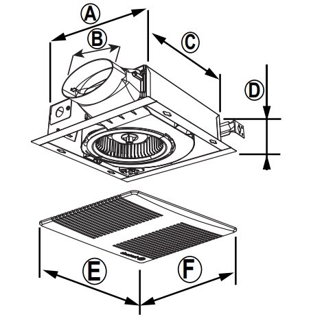
| A | B | C | D | E | F |
10 1/4 (260) |
4 (102) |
10 1/4 (260) |
3 3/8 (86) |
13 3/4 (321) |
13 (330) |
Dimensions are in inches (mm). |
|||||
GUIDE SPECIFICATION
Specifier Notes: This guide specification is written in Construction Specifications Institute (CSI) 3-Part Format in accordance with the CSI Construction Specifications Practice Guide, MasterFormat, SectionFormat, and PageFormat.
Specifier Notes: This Section must be carefully reviewed and edited by the Architect or Engineer to meet the requirements of the Project and local building code. Coordinate this Section with Division 01, other specification sections, and the Drawings. Delete all Specifier Notes after editing this Section.
Section numbers and titles are based on MasterFormat 2014 Update.
SECTION 23 34 23.06
CEILING MOUNTED EXHAUST FANS
Specifier Notes: This Section covers Fantech’s Bathfan Series of ceiling or wall mounted exhaust fans. Consult Fantech for assistance in editing this Section as required for the Project.
PART 1. GENERAL
1.1 SECTION INCLUDES
A. Ceiling or wall mounted exhaust fans
1.2 RELATED REQUIREMENTS
Specifier Notes: Edit the following list of related sections as required for the Project. Limit the list to sections with specific information that the reader might expect to find in this Section but is specified elsewhere.
A. Section 23 31 00 – HVAC Ducts and Casings.
B. Section 26 05 00 – Common Work Results for Electrical.
1.3 REFERENCE STANDARDS
Specifier Notes: List reference standards used elsewhere in this Section, complete with designations and titles. Delete reference standards from the following list not used in the edited Section.
A. Home Ventilating Institute (HVI) (www.hvi.org):
1. HVI Publication 915 – Procedure for Loudness Rating of Residential Fan Products
2. HVI Publication 916 – Air Flow Test Procedure
3. HVI Publication 920 Product Performance Certification Procedure Including Verification and Challenge
B. Air Movement and Control Association International (AMCA) (www.amca.org):
1. AMCA Publication 211 – Certified Ratings Program - Product Rating Manual for Fan Air Performance.
2. AMCA Standard 210 - ASHRAE 51 – Laboratory Methods of Testing Fans for Certified Aerodynamic Performance Rating
3. AMCA Standard 311- Certified Ratings Program- Product Rating Manual for Fan Sound Performance
C. ENERGY STAR (https://www.energystar.gov/)
D. ETL (https://www.intertek.com/marks/etl/)
1. Conforms to UL standard no. UL507
2. Conforms to CSA standard C22.2 113-18
1.4 PREINSTALLATION MEETINGS
Specifier Notes: Edit the Preinstallation Meetings article as required for the Project. Delete article if not required. Options are denoted by brackets.
A. Convene preinstallation meeting [1 week] [2 weeks] before start of Work of this Section.
B. Require attendance of parties directly affecting Work of this Section, including Contractor, Architect, installer, and manufacturer’s representative.
C. Review the Following:
a. Materials
b. Installation
c. Adjusting
d. Protection
e. Coordination with other Work
1.5 SUBMITTALS
Specifier Notes: Edit the Submittals article as required for the Project. Delete submittals not required.
A. Comply with Division 01.
B. Product Data: Submit the manufacturer’s product data, including installation instructions.
C. Shop Drawings: Submit the manufacturer’s shop drawings, including plans, elevations, sections, and details.
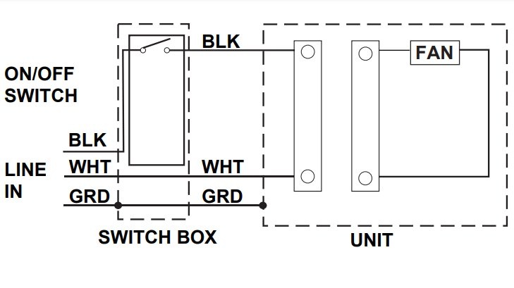
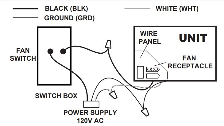
a. Wiring Diagrams: Indicate wiring for each item of equipment and interconnections between items of equipment.
b. Include manufacturer’s names, model numbers, ratings, power requirements, equipment layout, device arrangement, complete wiring point-to-point diagrams, and conduit layouts.
D. Manufacturer’s Certification: Submit the manufacturer’s certification that materials comply with specified requirements and are suitable for the intended application.
E. Operation and Maintenance Data:
a. Submit the manufacturer’s operation and maintenance manual; including the following:
i. Operation, maintenance, adjustment, and cleaning instructions.
ii. Troubleshooting guide
iii. Parts list
iv. Electrical wiring diagrams if required.
b. Provide detailed information required for the Owner to properly operate and maintain equipment.
F. Warranty Documentation: Submit the manufacturer’s standard warranty.
1.6 QUALITY ASSURANCE
A. Manufacturer’s Qualifications: Manufacturer regularly engaged in the manufacturing of circular inline duct fans to that specified for a minimum of 10 years.
B. Installer's Qualifications:
a. Installer regularly engaged in installation of bathroom exhaust fans of similar type to that specified for a minimum of 5 years.
b. Use persons trained for installation of bathroom exhaust fans.
1.7 DELIVERY, STORAGE, AND HANDLING
A. Delivery Requirements: Deliver materials to site in manufacturer’s original, unopened containers and packaging, with labels clearly identifying product name and manufacturer.
B. Storage and Handling Requirements:
a. Store and handle materials in accordance with manufacturer’s instructions.
b. Keep materials in manufacturer’s original, unopened containers and packaging until installation.
c. Store materials in clean, dry area indoors.
d. Keep materials from freezing.
e. Protect materials during storage, handling, and installation to prevent damage.
1.8 LIMITED FACTORY WARRANTY
Warranty Period: 5 years
PART 2. PRODUCTS
2.1 MANUFACTURERS
Specifier Notes: Specify if substitutions will be permitted. Options are denoted by brackets.
A. Manufacturer: Systemair MFG Inc., 10048 Industrial Blvd., Lenexa, Kansas 66215. Phone 800-747-6217. www.fantech.net. ussupport@fantech.net.
B. Substitutions: [Not permitted] [Comply with Division 01].
C. Single Source: Obtain exhaust fans from a single manufacturer.
2.2 CEILING MOUNTED EXHAUST FANS
Specifier Notes: Specify if substitutions will be permitted. Options are denoted by brackets.
A. [Bathfans: Must be of the alternating-current (AC) type: RCS80L]
1. Configuration: Ceiling bottom inlet grille and side outlet connection for 4–5 inch (101–127mm) round duct, as depicted on drawings
2. Casing: Constructed of 26-gauge, galvanized steel
3. Blower Wheel: Single wheel
4. Inlet Grille: Recessed white mil-grove baffle
5. Light: R30 ENERGY STAR® approved LED recessed light bulb with a 3000K warm white color.
6. Integrated soft-close backdraft damper
7. Suitable for ceiling mounting
8. Provide four 24-inch hanger bar mounting brackets
9. Motor Electrical Data:
a. Voltage: 120
b. Phase: 1
c. Hertz: 60
d. Watts: 19.7
e. Amperage: 0.25A
B. [Bathfans: Must be of the alternating-current (AC) type: Simple (SMPL) Series]
Specifier Notes: Specify whether exhaust fans will be installed in the ceiling or in the wall.
1. Configuration: Ceiling/Wall bottom inlet grille and side outlet connection for 4-inch (102mm) oval duct, as depicted on drawings
2. Casing: Constructed of 26-gauge, galvanized steel
3. Blower Wheel: Single wheel
4. Inlet Grille: White polymeric resin
5. [LED Lighted Grille color: 11W, 4000K cool white]
6. Integrated soft-close backdraft damper
7. Suitable for [ceiling] [wall] mounting
8. One 24-inch hanger bar mounting bracket included
9. Motor Electrical Data:
a. Voltage: 120
b. Phase: 1
c. Hertz: 60
d. Watts: [18.1] [26.1]
e. Amperage: [0.25] [0.30A]
C. [Bathfan: Must be of the direct-current (DC) type: Select Fit (SF) Series]
Specifier Notes: Specify whether ceiling mounted exhaust fans will be installed in the ceiling or in the wall.
1. Configuration: Ceiling/Wall bottom inlet grille and side outlet connection for 4-inch (102mm) oval duct, as depicted on drawings
2. Casing: Constructed of 26-gauge, galvanized steel
3. Blower Wheel: Single wheel
4. Inlet Grille: White polymeric resin
5. [LED Lighted Grille color: 11W, 4000K cool white]
6. Integrated soft-close backdraft damper
7. Suitable for [ceiling] [wall] mounting
8. One 24-inch hanger bar mounting bracket included
9. Motor Electrical Data:
a. Voltage: 120
b. Phase: 1
c. Hertz: 60
d. Watts: 12
e. Amperage: 0.25A
D. [Bathfan: Must be of the direct-current (DC) type: Select (S) Series]
1. Configuration: Ceiling bottom inlet grille and side outlet connection for 6-inch (152mm) round duct, as depicted on drawings
2. Casing: Constructed of 26-gauge, galvanized steel
3. Blower Wheel: Single wheel
4. Inlet Grille: White polymeric resin
5. [LED Lighted Grille color: 11W, 4000K cool white]
6. Integrated soft-close backdraft damper
7. Suitable for ceiling mounting only
8. One EZ Mounting Adjustable Frame included
9. Motor Electrical Data:
a. Voltage: 120
b. Phase: 1
c. Hertz: 60
d. Watts: [5.0] [6.8] [11.0] [7.4] [10.2] [11.6]
e. Amperage: [0.2] [0.25A]
E. [Bathfan: Must be of the direct-current (DC) type: COM200-300-400-500]
1. Configuration: Ceiling bottom inlet grille and side outlet connection for 8-inch (203mm) round duct, as depicted on drawings
2. Casing: Constructed of 26-gauge, galvanized steel
3. Blower Wheel: Single wheel
4. Inlet Grille: White polymeric resin
5. Integrated soft-close backdraft damper
6. Four hanger brackets included
7. Suitable for ceiling mounting only
8. Motor Electrical Data:
a. Voltage: 120
b. Phase: 1
c. Hertz: 60
d. Watts: [55] [68] [77] [95]
e. Amperage: 0.65A
F. Fan Capacities and Characteristics: Refer to Drawing schedule.
2.3 ACCESSORIES
Specifier Notes: Delete accessories not required. Options are denoted by brackets.
A. Duct Connector Reducer
1. Model: [4 inch oval x 3 inch round Reducer] [6 inch oval x 4 inch round Reducer]
a. Construction:
i. Plastic
B. External Electronic Timer
1. Model: FD60EM
a. Electronic push button timer switch for 10-, 20-, 30- and 60-minute timed operation of an exhaust fan
b. Voltage: 115V
c. Amperage: 20A
d. Enclosure class: IP54
C. Flex Duct
1. Model: [“FIDT 4”] [“FIDT 6”] [“FIDT 8”]
a. Insulated flexible ducts for indoor use in residential and commercial HVAC systems with low-to-medium operating pressure
b. Construction: Tri-directional fiberglass scrim reinforced, metallized polyester outer jacket
c. R Value: R4.2
d. Length: 25 feet (7.62 meters)
D. External Louver Exhaust
1. Model: [“HS 4W”] [“HS 6W”]
a. Plastic louvered shutter with duct connection
b. Length: [4 inch (102 mm)] [6 inch (152 mm)]
E. [Ceiling Radiation Damper – Small]
1. Model: Small
a. Construction:
i. Galvanized steel frame
ii. 165 degree Fahrenheit fusible link
b. Dimensions:
i. Length: 12 inches (305mm)
ii. Width: 12 inches (305mm)
iii. Height: 2-1/2 inches (64mm)
c. Fire Protection:
i. NFPA-90A
d. cULus Listed:
i. UL 555C listed for use in a 1-hour fire-rated wood truss ceiling designs
F. [Ceiling Radiation Damper – Large]
1. Model: Large
a. Construction:
i. Galvanized steel frame
ii. 165 degree Fahrenheit fusible link
b. Dimensions:
i. Length: 11-1/2 inches (292mm)
ii. Width: 12 inches (305mm)
iii. Height: 2-1/2 inches (64mm)
c. Fire Protection:
i. NFPA-90A
d. cULus Listed:
i. UL 555C listed for use in a 1-hour fire-rated wood truss ceiling designs
PART 3. EXECUTION
3.1 EXAMINATION
A. Examine areas to receive fans.
B. Notify the Architect of conditions that would adversely affect installation or subsequent use.
C. Do not begin installation until unacceptable conditions are corrected.
3.2 PROTECTION
A. Protect adjacent construction and finished surfaces during installation and testing.
B. Except for operational testing, do not operate fan during construction.
3.3 INSTALLATION
1. Install fans in accordance with the manufacturer’s instructions at locations indicated on the Drawings.
2. Attach ductwork to outlet connection collars of fans in accordance with the manufacturer’s instructions.
3. Electrical: Install electrical power to exhaust fans as specified in Section 26 05 00.
3.4 QUALITY CONTROL
1. Run test at factory.
3.5 ADJUSTING AND CLEANING
1. Adjust, clean, and maintain installed fan units in accordance with manufacturer's published instructions.
END OF SECTION


