


Back
Global site
Top duct connection HRV, 104 cfm + Turbo mode
Item #: 463333
The perfect trio of versatility, features, and efficiency, the FLEX®100H is ideal for high-rise apartment applications, condos, single and multi family homes.
• Airflow up to 104 cfm @ 0.4" wg.
Unlike traditional and bulky HRVs, which require excessive power to meet supplemental ventilation needs, Fantech’s compact, yet powerful, FLEX®100H allows for sizing based entirely on principal ventilation requirements.
With its exclusive TurboTouch feature, the Flex 100H can deliver increased exhaust capacity to easily meet supplemental ventilation needs whenever additional airflow is required.
With its compact top port design featuring 5 inch oval collars, and the included EZ-Mount wall bracket, the FLEX®100H can be installed in spaces as small as 24 inches, such as a closet or maintenance room. Additionally, the integrated airflow measurement system allows for quick and accurate airflow reads during installation.
In the Box
This appliance comes with a 104 cfm HRV, a wall bracket, and a drain hose kit.

| Product | ||
|---|---|---|
| Voltage (nominal) | 120 | V |
| Frequency | 60 | Hz |
| Phases | 1~ | |
| Input power | 168 | W |
| Input current | 1.6 | A |
| Air flow | 49 | L/s |
| Certificate | CSA. HVI |
| Exchanger | ||
|---|---|---|
| Heat exchanger | Heat recovery |
| Dimensions and weights | ||
|---|---|---|
| Weight | 42.9 | lb |
| Used for | ||
|---|---|---|
| Installation type | Vertical |
Supply temperature |
Net airflow |
Consumed power |
Sensible recovery efficiency |
Adjusted sensible recovery efficiency |
Latent recovery/ moisture transfer |
|
°F (°C) |
cfm (L/s) |
W |
% |
% |
||
Heating |
32 (0) |
62 (29) |
89 |
60 |
66 |
0.00 |
32 (0) |
78 (37) |
100 |
60 |
67 |
0.10 |
|
32 (0) |
100 (47) |
145 |
59 |
65 |
0.00 |
|
-13 (-25) |
66 (31) |
100 |
56 |
60 |
0.04 |
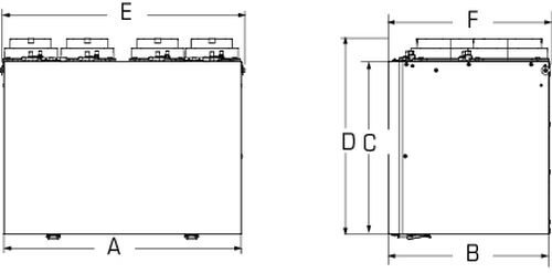
| A | B | C | D | E | F |
21 1/2 (546) |
14 1/2 (368) |
15 5/8 (397) |
17 7/8 (454) |
22 1/2 (572) |
15 (381) |
Dimensions in inches (mm). |
|||||
GUIDE SPECIFICATION
Specifier Notes: This guide specification is written in Construction Specifications Institute (CSI) 3-Part Format in accordance with The CSI Construction Specifications Practice Guide, MasterFormat, SectionFormat, and PageFormat.
Specifier Notes: This Section must be carefully reviewed and edited by the Architect or Engineer to meet the requirements of the Project and local building code. Coordinate this Section with Division 01, other specification sections, and the Drawings. Delete all Specifier Notes after editing this Section.
Section numbers and titles are based on MasterFormat 2016 Update.
SECTION 23 57 00
HEAT EXCHANGERS FOR HVAC
Specifier Notes: This Section covers Fantech’s FLEX 100H Heat Recovery Ventilators. Consult Fantech for assistance in editing this Section as required for the Project.
PART 1. GENERAL
1.1 SECTION INCLUDES
A. Heat Recovery Ventilators
1.2 RELATED REQUIREMENTS
Specifier Notes: Edit the following list of related sections as required for the Project. Limit the list to sections with specific information that the reader might expect to find in this Section but is specified elsewhere.
A. Section 23 08 00 – Commissioning of HVAC
1.3 REFERENCE STANDARDS
Specifier Notes: List reference standards used elsewhere in this Section, complete with designations and titles. Delete reference standards from the following list not used in the edited Section.
A. ANSI/AMCA 300 – Reverberant Room Method for Sound Testing of Fans
B. CSA C22.2, No. 113 – Fans and Ventilators
C. CSA C439 – Laboratory Methods of Test for Rating the Performance of Heat/Energy-Recovery Ventilators
D. CSA F326 – Residential Mechanical Ventilation Systems
E. IEC 60529 – Ingress Protection Test Standard
F. ISO 9001:2015 – Quality Management Systems – Requirements
G. NFPA 70 – National Electrical Code (NEC)
H. UL723 – Standard for Test for Surface Burning Characteristics of Building Materials
I. UL900 – Standard for Safety Air Filter Units
J. UL1004 – Standard for Safety Electric Motors
K. UL1812 – Standard for Ducted Heat Recovery Ventilators
1.4 PREINSTALLATION MEETINGS
Specifier Notes: Edit the Preinstallation Meetings article as required for the Project. Delete article if not required.
A. Convene preinstallation meeting [1 week] [2 weeks] before start of Work of this Section
B. Require attendance of parties directly affecting Work of this Section, including Contractor, Architect, installer, and manufacturer’s representative
C. Review the Following:
a. Materials
b. Installation
c. Adjusting
d. Protection
e. Coordination with other Work
1.5 SUBMITTALS
Specifier Notes: Edit the Submittals article as required for the Project. Delete submittals not required.
A. Comply with Division 01
B. Product Data: Submit manufacturer’s product data, including installation instructions
C. Shop Drawings: Submit manufacturer’s shop drawings, including plans, elevations, sections, and details
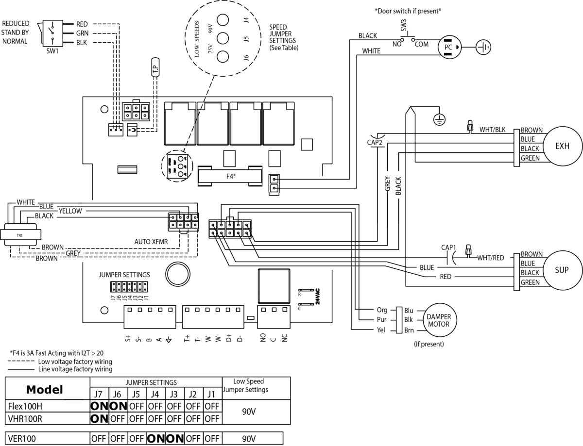
a. Wiring Diagrams: Indicate wiring for each item of equipment and interconnections between items of equipment
b. Include manufacturer’s names, model numbers, ratings, power requirements, equipment layout, device arrangement, complete wiring point-to-point diagrams, and conduit layouts
D. Manufacturer’s Certification: Submit manufacturer’s certification that materials comply with specified requirements and are suitable for intended application
E. Operation and Maintenance Data:
a. Submit manufacturer’s operation and maintenance manual; including the following:
i. Operation, maintenance, adjustment, and cleaning instructions
ii. Troubleshooting guide
iii. Parts list
iv. Electrical wiring diagrams if required
b. Provide detailed information required for Owner to properly operate and maintain equipment
F. Warranty Documentation: Submit manufacturer’s standard warranty
1.6 QUALITY ASSURANCE
A. Manufacturer’s Qualifications:
a. Manufacturer regularly engaged in the manufacturing of air handling units, heat, or energy recovery ventilators in the last 10 years
b. ISO 9001 Certified
B. Installer's Qualifications:
a. Installer regularly engaged in installation of air handling units, heat, or energy recovery ventilators to that specified for a minimum of 5 years
b. Use persons trained for installation of air handling units, heat or energy recovery ventilators
1.7 DELIVERY, STORAGE, AND HANDLING
A. Delivery Requirements: Deliver materials to site in manufacturer’s original, unopened containers, and packaging, with labels clearly identifying product name and manufacturer
B. Storage and Handling Requirements:
a. Store and handle materials in accordance with manufacturer’s instructions
b. Keep materials in manufacturer’s original, unopened containers, and packaging until installation
c. Store materials in clean, dry area indoors
d. Keep materials from freezing
e. Protect materials during storage, handling, and installation to prevent damage
1.8 WARRANTY
Warranty Period: Limited lifetime on aluminum core, 7 years on motors, and 5 years on parts.
PART 2. PRODUCTS
2.1 MANUFACTURERS
A. Manufacturer: Fantech Inc., 50 Kanalflakt Way, Bouctouche, New Brunswick E4S 3M5, Canada For Canada: Toll Free 800-565-3548, CANADAsupport@fantech.net For USA: Toll Free 800-747-1762, USsupport@fantech.net Specifier Notes: Specify if substitutions will be permitted.
B. Substitutions: [Not permitted] [Comply with Division 01]
C. Single Source: Provide materials from single manufacturer
2.2 HEAT RECOVERY VENTILATORS
A. Heat Recovery Ventilators:
a. Model: FLEX 100H
b. Indoor, compact, residential Heat Recovery Ventilators
Specifier Notes: Specify required model. Consult Fantech for assistance in determining Heat Recovery Ventilator model for the specific application.
B. General
a. Each Unit or Group of Units: Capable of operating in any mode independently or dependently of other systems
b. Listed under CSA C22.2, No. 113/UL 1812
c. Wiring: NFPA 70
d. Performance: As scheduled on the Drawings
e. Equipped with a control system
f. Performs all functions necessary for operation
g. Capable of changing modes with no interruption to system operation
h. Capable of transferring sensible heat between the fresh and stale air streams
i. Capable of operating in winter and summer conditions without imbalance or loss of ventilation capacity greater than specified in design
C. Unit Cabinet
a. Single Wall Cabinet:
i. 22-gauge galvanized pre-painted steel corrosion resistant casing
ii. Seams: Sealed, requiring no caulking in field
b. Insulation within a Single Wall:
i. 1.0-in. (25-mm) of high-density expanded polystyrene
ii. Flame Spread Index, UL 723: Not over 25
iii. Smoke Developed Index, UL 723: Not over 50
D. Cabinet Doors & Panels
a. 22-gauge galvanized pre-painted door
b. 1.0-in. (25-mm) of high-density expanded polystyrene
E. Fans
a. Factory-balanced fans with backward curved blades
b. Fan Motors:
i. Maintenance-free, permanently lubricated, sealed ball bearings
ii. Thermal overload protected (TOP)
iii. UL listed to UL1004 and/or UL2111, CSA C22.2 No. 77 and No.100
iv. IP Protection: Class 44 according to IEC 60529
c. Separate fans for exhaust and supply blowers
F. Heat recovery core
a. Construction: Aluminum frame with flame rated plastic plates which are designed to transfer sensible heat. The flame spread index of the heat recovery exchanger shall not be over 25 and its smoke developed index shall not be over 50 when tested in accordance with the Standard for Tests for Surface Burning Characteristics of Building Material, UL723. The HRV Core is freeze tolerant and water washable
b. Cross-flow construction type
c. Frame Material: Aluminum
d. Flame Spread Index, heat recovery exchanger, UL 723: Not over 25
e. Smoke Developed Index, heat recovery exchanger, UL 723: Not over 50
G. Air filters
a. Supply and exhaust air protected by 2 MERV-3 washable electrostatic panel type air filters
b. Optional MERV-8 supply air filters can be added and used along with the standard MERV-3
H. Frost prevention
a. Frost prevention sequence (pre-set) initiated if the outdoor air temperature falls below the set point of 23°F (-5°C)
I. Electrical 1 Phase Input Voltage
a. Electrical Power: 120 VAC, 1 Phase, 60 Hz, MOP 15A
b. Internal Electrical Components:
i. Factory wired for single-point power connection
ii. UL Listed or Recognized and CSA Certified or Accepted where applicable and wired in compliance with the National Electrical Code
J. Electrical Box Components: Accessible without stopping unit or opening doors
K. Electrical Box:
a. Isolated from airflow paths
b. Protect integral wires and connections
L. Serviceability
a. Access Panel: Hinged and/or screwed access panel on front of unit
b. Heat recovery exchangers, filters, and motors: serviceable from front of unit
c. Fan Assemblies: mounted on removable sliding base
d. Heat recovery exchangers and filters: mounted on slide-out rails
2.3 ACCESSORIES
A. TVOC Sensing Control: model ECO-Touch Auto IAQ
B. Insulated Flex Duct: model FIDT 5
C. Plastic Supply/Exhaust Hoods: model COM5P
D. Metal Supply Grill: model MGS 5
E. Metal Exhaust Grill: model MGE 5
2.4 ASSEMBLY
A. Factory assembled and wired heat recovery ventilators
2.5 SOURCE QUALITY CONTROL
A. Run test at factory
PART 3. EXECUTION
3.1 EXAMINATION
A. Examine areas to receive heat recovery ventilators
B. Notify Architect of conditions that would adversely affect installation or subsequent use
C. Do not begin installation until unacceptable conditions are corrected
3.2 PREPARATION
A. Prepare surfaces where heat recovery ventilators are to be mounted
B. Ensure surfaces are flat, level, plumb, and can support weight of heat recovery ventilators
3.3 INSTALLATION
A. Install heat recovery ventilators in accordance with manufacturer’s instructions at locations indicated on the Drawings
B. Unit is typically hung by using metal mounting bracket supplied with unit.
C. Optional chain kit available
D. Install heat recovery ventilators in accordance with NFPA 70
E. Do not expose electronic components to temperatures below 32 degrees F (0 degrees C) or above 122 degrees F (50 degrees C)
3.4 ADJUSTING
A. Adjust heat recovery ventilators for proper operation in accordance with manufacturer’s instructions
3.5 DEMONSTRATION
A. Demonstration
a. Demonstrate that heat recovery ventilators function properly in every respect
b. Provide hands-on demonstrations of operation of system components and complete system, including user-level program changes and function
c. Provide instruction and training by factory-trained and certified representative of manufacturer
3.6 PROTECTION
A. Protect installed heat recovery ventilators from damage during construction
END OF SECTION
TVOC sensing controller, multi-function, touchscreen,4 wires


