


Retour
Site global
CXN du conduit (latéral) ERV, 468 pcm
Numéro article: 99266

| Unité | ||
|---|---|---|
| Fréquence | 60 | Hz |
| Tension (nominale) | 120 | V |
| Phases | 1~ | |
| Intensité | 4.17 | A |
| MCA | 6.88 | A |
| MOP | 15 | A |
| Puissance installée | 500 | W |
| Débit d'air | max 221 | L/s |
| Pression statique nominale max (in. w.g) | 100 | Pa |
| Autres | ||
|---|---|---|
| Type d'installation | Horizontal |
| Dimensions et Poids | ||
|---|---|---|
| Poids | 132.3 | lb |
| Certificats | ||
|---|---|---|
| Certificat | CSA, AHRI 1060 Components |
Température d'air frais |
Débit d'air net |
Efficacité sensible net |
Efficacité latente net |
Efficactié totale net |
|
°F (°C) |
pcm (L/s) |
% |
% |
% |
|
Chauffage |
35 (1.7) |
300 (142) |
63 |
46 |
59 |
35 (1.7) |
225 (106) |
66 |
51 |
64 |
|
Refroidissement |
95 (35) |
300 (142) |
63 |
420 |
58 |
95 (35) |
225 (142) |
69 |
48 |
63 |
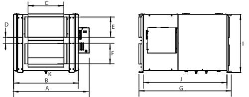
| A | B | C | D | E | F | G | I | J | K (Drain) |
29 1/2 (747) |
25 1/8 (639) |
14 (355) |
2 1/2 (64) |
8 (203) |
8 (203) |
35 15/16 (911) |
22 11/16 (577) |
32 1/2 (826) |
1/2 (13) |
Dimensions en pouces (mm). |
|||||||||
GUIDE SPECIFICATION
Specifier Notes: This guide specification is written in Construction Specifications Institute (CSI) 3-Part Format in accordance with The CSI Construction Specifications Practice Guide, MasterFormat, SectionFormat, and PageFormat.
Specifier Notes: This Section must be carefully reviewed and edited by the Architect or Engineer to meet the requirements of the Project and local building code. Coordinate this Section with Division 01, other specification sections, and the Drawings. Delete all Specifier Notes after editing this Section.
Section numbers and titles are based on MasterFormat 2016 Update.
SECTION 23 72 00
Specifier Notes: This Section covers Fantech’s SER Series of Energy Recovery Ventilators. Consult Fantech for assistance in editing this Section as required for the Project.
PART 1. GENERAL
1.1 SECTION INCLUDES
A. Energy Recovery Ventilators
1.2 RELATED REQUIREMENTS
Specifier Notes: Edit the following list of related sections as required for the Project. Limit the list to sections with specific information that the reader might expect to find in this Section but is specified elsewhere.
A. Section 23 08 00 – Commissioning of HVAC
1.3 REFERENCE STANDARDS
Specifier Notes: List reference standards used elsewhere in this Section, complete with designations and titles. Delete reference standards from the following list not used in the edited Section.
A. ANSI/AHRI 1060 Components – Performance Rating of Air-to-Air Heat Exchangers for Energy Recovery Ventilation Components.
B. ANSI/AMCA 300 – Reverberant Room Method for Sound Testing of Fans.
C. ASHRAE 84 – Method of Testing Air-to-Air Heat Exchangers.
D. ASTM A 792/A 792M – Standard Specification for Steel Sheet, 55 % Aluminum-Zinc Alloy-Coated by the Hot-Dip Process.
E. CSA C22.2, No. 77 – Motors with Inherent Overheating Protection.
F. CSA C22.2, No. 100 – Motors and Generators.
G. CSA C22.2, No. 113 – Fans and Ventilators.
H. CSA C22.2, No. 236 – Heating and Cooling Equipment.
I. ISO 9001:2015 – Quality Management Systems – Requirements.
J. NFPA 70 – National Electrical Code (NEC).
K. UL 723 – Standard for Test for Surface Burning Characteristics of Building Materials.
L. UL 900 – Standard for Air Filter Units.
M. UL 1004-2 – Standard for Impedance Protected Motors.
N. UL 1004-3 – Standard for Thermally Protected Motors.
O. UL 1004-7 – Standard for Electronically Protected Motors.
P. UL 1812 – Standard for Ducted Heat Recovery Ventilators.
Q. UL 2111 – Standard for Overheating Protection for Motors.
1.4 PREINSTALLATION MEETINGS
Specifier Notes: Edit the Preinstallation Meetings article as required for the Project. Delete article if not required.
A. Convene preinstallation meeting [1 week] [2 weeks] before start of Work of this Section.
B. Require attendance of parties directly affecting Work of this Section, including Contractor, Architect, installer, and manufacturer’s representative.
C. Review the Following:
1. Materials
2. Installation
3. Adjusting
4. Protection
5. Coordination with other Work
1.5 SUBMITTALS
Specifier Notes: Edit the Submittals article as required for the Project. Delete submittals not required.
A. Comply with Division 01.
B. Product Data: Submit manufacturer’s product data, including installation instructions.
C. Shop Drawings: Submit manufacturer’s shop drawings, including plans, elevations, sections, and details.
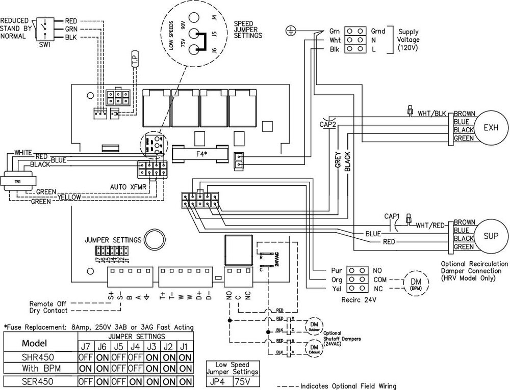
1. Wiring Diagrams: Indicate wiring for each item of equipment and interconnections between items of equipment.
2. Include manufacturer’s names, model numbers, ratings, power requirements, equipment layout, device arrangement, complete wiring point-to-point diagrams, and conduit layouts.
D. Manufacturer’s Certification: Submit manufacturer’s certification that materials comply with specified requirements and are suitable for intended application.
E. Operation and Maintenance Data:
1. Submit manufacturer’s operation and maintenance manual; including the following:
a. Operation, maintenance, adjustment, and cleaning instructions.
b. Troubleshooting guide
c. Parts list
d. Electrical wiring diagrams if required.
2. Provide detailed information required for Owner to properly operate and maintain equipment.
F. Warranty Documentation: Submit manufacturer’s standard warranty.
1.6 QUALITY ASSURANCE
A. Manufacturer’s Qualifications:
1. Manufacturer regularly engaged in the manufacturing of air handling units, heat or energy recovery ventilators in the last 10 years.
2. ISO 9001 Certified
B. Installer's Qualifications:
1. Installer regularly engaged in installation of air handling units, heat or energy recovery ventilators to that specified for a minimum of 5 years.
2. Use persons trained for installation of air handling units, hear or energy recovery ventilators
1.7 DELIVERY, STORAGE, AND HANDLING
A. Delivery Requirements: Deliver materials to site in manufacturer’s original, unopened containers, and packaging, with labels clearly identifying product name and manufacturer.
B. Storage and Handling Requirements:
1. Store and handle materials in accordance with manufacturer’s instructions.
2. Keep materials in manufacturer’s original, unopened containers, and packaging until installation.
3. Store materials in clean, dry area indoors.
4. Keep materials from freezing.
5. Protect materials during storage, handling, and installation to prevent damage.
1.8 WARRANTY
Warranty Period: 3 years
PART 2. PRODUCTS
2.1 MANUFACTURERS
A. Manufacturer: Fantech Inc., 50 Kanalflakt Way, Bouctouche, New Brunswick E4S 3M5, Canada.
For Canada: Toll Free 800-565-3548, CANADAsupport@fantech.net
For USA: Toll Free 800-747-1762, USsupport@fantech.net
Specifier Notes: Specify if substitutions will be permitted.
B. Substitutions: [Not permitted] [Comply with Division 01].
C. Single Source: Provide materials from single manufacturer.
2.2 ENERGY RECOVERY VENTILATORS
A. Energy Recovery Ventilators: SER Series
1. Models: SER450, SER700, SER1100, SER1300
2. Indoor, compact, light-commercial energy recovery ventilators
Specifier Notes: Specify required model. Consult Fantech for assistance in determining energy recovery ventilator model for the specific application.
B. General
3. Each Unit or Group of Units: Capable of operating in any mode independently or dependently of other systems.
4. Listed under CSA C22.2, No. 113-15/UL 1812.
5. Wiring: NFPA 70.
6. Performance: As scheduled on the Drawings.
7. Equipped with a control system
8. Perform all functions necessary for operation.
9. Ventilation to Building: Not to cease in any mode based solely on operational temperature of minus 13 to 104 degrees F (minus 25 to 40 degrees C).
10. Capable of changing modes with no interruption to system operation.
11. Capable of transferring both sensible and latent heat between the fresh and stale air streams.
12. Capable of operating in winter and summer conditions without imbalance or loss of ventilation capacity greater than specified in design.
C. Unit Cabinet
13. Single Wall Cabinet:
a. 22-gauge sheet galvanized steel, G90 coated with lapped corners.
b. Seams: Sealed, requiring no caulking in field.
14. Insulation within a Single Wall:
a. 1.0-inch (25.4-mm) fiberglass.
b. Flame Spread Index, UL 723: Not over 25.
c. Smoke Developed Index, UL 723: Not over 50.
D. Cabinet Doors & Panels
d. 22-gauge G90 pre-painted sheet galvanized steel.
e. 1.0-inch (25.4-mm) fiberglass.
E. Fans
15. Direct-drive, backward-inclined, motorized impellers
16. Fan Motors:
a. Maintenance-free, permanently lubricated, sealed ball bearings.
b. Thermal overload protected (TOP).
c. UL listed to UL1004 and/or UL2111, CSA C22.2 No. 77 and No.100
d. IP Protection: Class 44.
17. Separate fans for exhaust and supply blowers.
F. Energy recovery exchanger
18. Exchanger Construction: Flame rated polymer membrane which is designed to transfer sensible and latent energy. The flame spread index of the energy recovery exchanger shall not be over 25 and its smoke developed index shall not be over 50 when tested in accordance with the Standard for Tests for Surface Burning Characteristics of Building Material, UL723. Mold and Bacteria resistance tested to ISO 846a and ISO 846c with a rating of 0 for both. Freeze tolerant tested to 40 freeze thaw cycles from –20°C to +20°C while maintaining both the energy recovery effectiveness and 0% EATR rating. The ERV exchangers are water washable.
19. Cross-flow construction type.
20. Performance: Certified and listed by AHRI 1060 Components.
21. Frame Material: Corner profiles in PVC and gables in aluminum-zinc sheet steel
22. Effectiveness of exchanger: Documented in accordance with ASHRAE 84 and AHRI 1060 Components.
23. Flame Spread Index, Energy Recovery Exchanger, UL 723: Not over 25.
24. Smoke Developed Index, Energy Recovery Exchanger, UL 723: Not over 50.
G. Air filters
25. Supply and exhaust air protected by MERV3 mesh filters constructed to meet UL 900. (Optional MERV8 or MERV13 filters are direct replacement to the MERV3 in size)
H. Frost control
26. Frost control sequence (pre-set) initiated if the outdoor air temperature falls below the set point of 23°F (-5°C)
J. Electrical 1 Phase Input Voltage
27. Electrical Power: 120 VAC, 1 Phase, 60 Hz, MOP 15A
28. Internal Electrical Components:
a. Factory wired for single-point power connection.
b. UL Listed or Recognized and CSA Certified or Accepted where applicable and wired in compliance with the National Electrical Code.
29. Electrical Box Components: Accessible without stopping unit or opening doors.
30. Electrical Box:
a. Isolated from airflow paths.
b. Protect integral wires and connections.
I. Serviceability
31. Access Panel: Hinged and/or screwed access panel on front of unit.
32. Energy Recovery Exchangers, Filters, and Motors: Serviceable from front of unit.
33. Fan Assemblies: Mounted on removable base.
34. Energy Recovery Exchangers and Filters: Mounted on slide-out rails.
2.3 ACCESSORIES
A. Shutter damper with spring-return actuators for Rectangular Ducts
Specifier Notes: Delete accessories not required.
1. Model: [“EFD 14-8”] [“EFD 20-8”] [“EFD 24-8”]
2. Spring-return actuators: motorized, 24 V motors with spring-return actuators.
3. Leakage: less than 1%
2.4 ASSEMBLY
A. Factory assembled and wired energy recovery ventilators
2.5 SOURSE QUALITY CONTROL
A. Run test at factory
PART 3. EXECUTION
3.1 EXAMINATION
A. Examine areas to receive energy recovery ventilators.
B. Notify Architect of conditions that would adversely affect installation or subsequent use.
C. Do not begin installation until unacceptable conditions are corrected.
3.2 PREPARATION
A. Prepare surfaces where energy recovery ventilators are to be mounted.
B. Ensure surfaces are flat, level, plumb, and can support weight of energy recovery ventilators
3.3 INSTALLATION
A. Install energy recovery ventilators in accordance with manufacturer’s instructions at locations indicated on the Drawings
B. Install energy recovery ventilators in accordance with NFPA 70
C. Install energy recovery ventilators, rod mount or seat on a platform, level, plumb, and secure.
D. Do not expose electronic components to temperatures below 32 degrees F (0 degrees C) or above 122 degrees F (50 degrees C).
3.4 ADJUSTING
A. Adjust energy recovery ventilators for proper operation in accordance with manufacturer’s instructions.
3.5 DEMONSTRATION
A. Demonstration
1. Demonstrate that energy recovery ventilators function properly in every respect
2. Provide hands-on demonstrations of operation of system components and complete system, including user-level program changes and function
3. Provide instruction and training by factory-trained and certified representative of manufacturer
3.6 PROTECTION
A. Protect installed energy recovery ventilators from damage during construction.
END OF SECTION
| Nom du document | Type de document | |
|---|---|---|
| E1864 Light Commercial Brochure FR | Brochure | |
| E400030 SER450 fiche de soumission.pdf | Brochure | |
| E400047 SHR 450 - SER 450 Dimensional Submittal.pdf | Brochure | |
| 444566 Light Commercial SER IOM EN FR.pdf | Manuel | |
| SHR 450, SER 450 .dxf | ficher CAD | |
| SHR450-SER450 Revit file.dxf | ficher CAD | |
| 444569 SER 450 fiche technique.pdf | Fiches Techniques |
Transmetteur de CO2 et de température adapté (montage mural)
LCD touch multi-function, IAQ sensing&wireless timer, 4 wire
MERV13 filter kit LC, 260-450 cfm, 4 pcs, 11.5"x11.4"
MERV8 filter kit LC, 260-450 cfm, 4 pcs 11.5"x11.4"
Grille métal de 4" de conduit ac collet, échappement
Grille métal de conduit 5" ac collet, échappement
Grille métal de conduit 8" ac collet, échappement
Grille métal de conduit 6" ac collet, alimentation
Grille métal de conduit 8" ac collet, alimentation


