


Retour
Site global
10" Vent., échappement, mur ext., blanc, 120V, 1~
Numéro article: 44865
Ce ventilateur de l'extérieur évacue l'air vicié, humide et pollué des espaces à l'intérieur. Les exemples d'application comprennent les salles de bains, les locaux de service, les garages résidentiels, etc.
• L'installation à l'extérieur garantit que le bruit du moteur reste à l'extérieur
• Le boîtier galvanisé avec un couvercle peint minimise le risque de corrosion
• Fonctionne dans des températures de l'air allant jusqu'à 60°C
• Les joints en néoprène assurent une fuite minimale dans les zones à haute température
• Protection intégrée contre les surcharges thermiques avec réinitialisation automatique.
• Joint en caoutchouc pour faciliter l'installation du conduit
• Garantie du fabricant de cinq ans
Avec le moteur dans le flux d'air, le ventilateur RVF assure une dissipation constante de la chaleur accumulée, même à charge partielle, ce qui permet au ventilateur d'atteindre une longévité et une fiabilité exceptionnelles, couvertes par une garantie parmi les meilleures du secteur.
| Données nominales | ||
|---|---|---|
| Tension (nominale) | 120 | V |
| Fréquence | 60 | Hz |
| Phases | 1~ | |
| Puissance installée | 207 | W |
| Intensité | 1.78 | A |
| Vitesse de rotation | 1 688 | tr/min |
| Débit d'air | max 503 | L/s |
| Température air en mouvement | max 40 | °C |
| Temp. max. avec variateur | 40 | °C |
| Protection/Classification | ||
|---|---|---|
| Classe d'étanchéité, moteur | IP44 | |
| Classe d'isolation | B |
| Dimensions et Poids | ||
|---|---|---|
| Conduit Circul d'aspiration | 10 | po. |
| Conduit Circul de refoulement | 10 | po. |
| Poids | 31.4 | lb |
| Option | ||
|---|---|---|
| Type de connexion | Circulaire | |
| Type de moteur | AC |
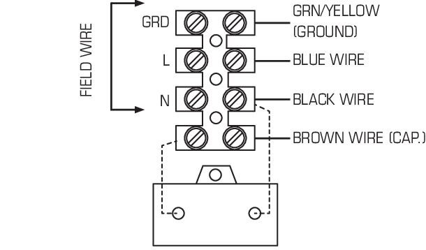
Tableau de débit d'air (CFM) |
|||||||||||||
Modèle |
Puissance nominale |
Tension / Phase |
Ampère max. |
RPM |
0.0"Ps |
0.2"Ps |
0.4"Ps |
0.6"Ps |
0.8"Ps |
1.0"Ps |
1.5"Ps |
Sones |
Max Ps |
W |
V/~ |
A |
min-1 |
PCM |
|||||||||
RVF 102) |
112 |
120/1 |
0.94 |
1500 |
793 |
706 |
309 |
495 |
356 |
242 |
- |
11.1† |
1.28 |
RVF 10L2) |
211 |
120/1 |
2.10 |
1700 |
1065 |
988 |
912 |
832 |
736 |
621 |
214 |
14.8† |
1.68 |
RVF 10XL2) |
312 |
120/1 |
2.61 |
1600 |
1248 |
1161 |
1068 |
972 |
875 |
764 |
384 |
16.0‡ |
1.94 |
La performance certifiée est pour une installation de type entrée à conduit C, sortie libre. |
|||||||||||||
Les cotes de performance n'incluent pas les effets des accessoires (accessoires). |
|||||||||||||
La vitesse (tr / min) est nominale. La performance est basée sur la vitesse de test actuelle. |
|||||||||||||
Les cotes sonores indiquées sont des valeurs de sonie en sones de ventilateur à 1,5 m (5 pi) dans un champ libre hémisphérique calculé selon la norme internationale AMCA 301. |
|||||||||||||
Les valeurs indiquées sont pour: Type d'installation C: niveaux de sone hémisphérique à sortie libre. |
|||||||||||||
† Les sons sont calculés à 0,2 ”(pression statique en pouces W.G.) |
|||||||||||||
‡ Les sons sont calculés à 0,4 ”(pression statique en pouces W.G.) |
|||||||||||||
2) Performance AMCA et sécurité cULus certifiés. |
|||||||||||||
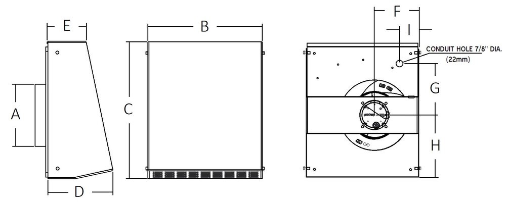
| Model | A | B | C | D | E | F | G | H | I |
RVF 10 |
10 (254) |
17 7/8 (454) |
21 1/4 (540) |
10 (254) |
5 7/8 (149) |
7 3/8 (188) |
8 1/16 (205) |
9 1/8 (232) |
2 3/4 (70) |
RVF 10L |
10 (254) |
17 7/8 (454) |
21 1/4 (540) |
10 (254) |
5 7/8 (149) |
8 1/8 (206) |
8 1/16 (205) |
9 1/8 (232) |
2 3/4 (70) |
RVF 10XL |
10 (254) |
17 7/8 (454) |
21 1/4 (540) |
10 (254) |
5 7/8 (149) |
8 1/8 (206) |
8 1/16 (205) |
9 1/8 (232) |
2 3/4 (70) |
Dimensions in inches (mm) |
|||||||||
GUIDE SPECIFICATION
Specifier Notes: This guide specification is written in Construction Specifications Institute (CSI) 3-Part Format in accordance with The CSI Construction Specifications Practice Guide, MasterFormat, SectionFormat, and PageFormat.
Specifier Notes: This Section must be carefully reviewed and edited by the Architect or Engineer to meet the requirements of the Project and local building code. Coordinate this Section with Division 01, other specification sections, and the Drawings. Delete all Specifier Notes after editing this Section.
Section numbers and titles are based on MasterFormat 2014 Update.
SECTION 23 34 00
HVAC FANS
Specifier Notes: This Section covers Fantech RVF Series wall mount exhaust fans with alternating current (AC) motors. Consult Fantech for assistance in editing this Section as required for the Project.
PART 1. GENERAL
1.1 SECTION INCLUDES
A. Wall mount exhaust fans with alternating current (AC) motors.
1.2 RELATED REQUIREMENTS
Specifier Notes: Edit the following list of related sections as required for the Project. Limit the list to sections with specific information that the reader might expect to find in this Section but is specified elsewhere.
A. Section 23 31 00 – HVAC Ducts and Casings.
B. Section 26 05 00 – Common Work Results for Electrical.
1.3 REFERENCE STANDARDS
Specifier Notes: List reference standards used elsewhere in this Section, complete with designations and titles. Delete reference standards from the following list not used in the edited Section.
A. Air Movement and Control Association International (AMCA) (www.amca.org):
1. AMCA 211 – Certified Ratings Program - Product Rating Manual for Fan Air Performance.
B. Underwriting Laboratory (UL) (https://productiq.ulprospector.com/en):
1. UL 507- Electric Fans
2. CSA 22.2 No 113- Fans and Ventilators
1.4 PREINSTALLATION MEETINGS
Specifier Notes: Edit the Preinstallation Meetings article as required for the Project. Delete article if not required.
A. Convene preinstallation meeting [1 week] [2 weeks] before start of Work of this Section.
B. Require attendance of parties directly affecting Work of this Section, including Contractor, Architect, installer, and manufacturer’s representative.
C. Review the Following:
1. Materials
2. Installation
3. Adjusting
4. Protection
5. Coordination with other Work
1.5 SUBMITTALS
Specifier Notes: Edit the Submittals article as required for the Project. Delete submittals not required.
A. Comply with Division 01.
B. Product Data: Submit manufacturer’s product data, including installation instructions.
C. Shop Drawings: Submit manufacturer’s shop drawings, including plans, elevations, sections, and details.
1. Wiring Diagrams: Indicate wiring for each item of equipment and interconnections between items of equipment.
2. Include manufacturer’s names, model numbers, ratings, power requirements, equipment layout, device arrangement, complete wiring point-to-point diagrams, and conduit layouts.
D. Manufacturer’s Certification: Submit manufacturer’s certification that materials comply with specified requirements and are suitable for intended application.
E. Operation and Maintenance Data:
1. Submit manufacturer’s operation and maintenance manual; including the following:
a. Operation, maintenance, adjustment, and cleaning instructions.
b. Troubleshooting guide
c. Parts list
d. Electrical wiring diagrams if required.
2. Provide detailed information required for Owner to properly operate and maintain equipment.
F. Warranty Documentation: Submit manufacturer’s standard warranty.
1.6 QUALITY ASSURANCE
A. Manufacturer’s Qualifications: Manufacturer regularly engaged in the manufacturing of wall mount exhaust fans to that specified for a minimum of 10 years.
B. Installer's Qualifications:
1. Installer regularly engaged in installation of wall mount exhaust fans of similar type to that specified for a minimum of 5 years.
2. Use persons trained for installation of wall mount exhaust fans.
1.7 DELIVERY, STORAGE, AND HANDLING
A. Delivery Requirements: Deliver materials to site in manufacturer’s original, unopened containers and packaging, with labels clearly identifying product name and manufacturer.
B. Storage and Handling Requirements:
1. Store and handle materials in accordance with manufacturer’s instructions.
2. Keep materials in manufacturer’s original, unopened containers and packaging until installation.
3. Store materials in clean, dry area indoors.
4. Keep materials from freezing.
5. Protect materials during storage, handling, and installation to prevent damage.
1.8 WARRANTY
Warranty Period: 5 years
PART 2. PRODUCTS
2.1 MANUFACTURERS
A. Manufacturer: Fantech Inc., 10048 Industrial Blvd., Lenexa, Kansas 66215. Phone 800-747-6217. www.fantech.net. ussupport@fantech.net.
Specifier Notes: Specify if substitutions will be permitted.
B. Substitutions: [Not permitted] [Comply with Division 01].
C. Single Source: Provide materials from single manufacturer.
2.2 HVAC FANS
A. Wall mount exhaust fans with alternating current (AC) motors: RVF Series
1. AMCA Air Seal
2. cULus Listed
A. Additional Evaluation(s): Outdoor Use
Specifier Notes: Specify wall mount exhaust fans models as required for the Project. Delete models not required.
B. Model: “RVF 10”
1. Inlet Diameter: 10 inches
2. Housing Dimensions: 21-1/4 inches x 17-7/8 inches x 10 inches (H x W x D)
3. Inlet Connection Collar: 1 inch with a rubber gasket
4. Casing Material: Galvanized Sheet Metal, powder coated, white, RAL9016. Allows to open the cover for maintenance if required
5. Motor: Alternating current external-rotor motor
6. Speed Control: by altering supply voltage via an external stepless controller
7. Motor Protection: electronically protected
8. Blades: Backward curved
9. Voltage: 120 V
10. Frequency: 50/60 Hz
11. Nominal Voltage Range: 100 to 130 V
12. Phase: 1
13. Maximum Airflow: 792 cfm
14. RPM: 1,458
15. Power Rating, Motor: 113 W
16. Current: 0.95 A
17. Operational Temperature: minus 13 to 104 degrees F
18. Weight: 27.1 lbs
19. Motor Insulation Class: B
20. Motor Enclosure Class: IP44
C. Model: “RVF 10L”
1. Inlet Diameter: 10 inches
2. Housing Dimensions: 21-1/4 inches x 17-7/8 inches x 10 inches (H x W x D)
3. Inlet Connection Collar: 1 inch with a rubber gasket
4. Casing Material: Galvanized Sheet Metal, powder coated, white, RAL9016. Allows to open the cover for maintenance if required
5. Motor: Alternating current external-rotor motor
6. Speed Control: by altering supply voltage via an external stepless controller
7. Motor Protection: electronically protected
8. Blades: Backward curved
9. Voltage: 120 V
10. Frequency: 50/60 Hz
11. Nominal Voltage Range: 100 to 130 V
12. Phase: 1
13. Maximum Airflow: 1,066 cfm
14. RPM: 1,688
15. Power Rating, Motor: 207 W
16. Current: 1.78 A
17. Operational Temperature: minus 13 to 104 degrees F
18. Weight: 31.4 lbs
19. Motor Insulation Class: B
20. Motor Enclosure Class: IP44
C. Model: “RVF 10XL”
1. Inlet Diameter: 10 inches
2. Housing Dimensions: 21-1/4 inches x 17-7/8 inches x 10 inches (H x W x D)
3. Inlet Connection Collar: 1 inch with a rubber gasket
4. Casing Material: Galvanized Sheet Metal, powder coated, white, RAL9016. Allows to open the cover for maintenance if required
5. Motor: Alternating current external-rotor motor
6. Speed Control: by altering supply voltage via an external stepless controller
7. Motor Protection: electronically protected
8. Blades: Backward curved
9. Voltage: 120 V
10. Frequency: 50/60 Hz
11. Nominal Voltage Range: 100 to 130 V
12. Phase: 1
13. Maximum Airflow: 1,248 cfm
14. RPM: 1,526
15. Power Rating, Motor: 309 W
16. Current: 2.59 A
17. Operational Temperature: minus 13 to 104 degrees F
18. Weight: 9.8 lbs
19. Motor Insulation Class: B
20. Motor Enclosure Class: IP44
2.3 ACCESSORIES
A. Silencer for Circular Duct
Specifier Notes: Delete accessories not required.
1. Model: [“LD 10”]
2. Insulation Thickness: 2 inches.
B. Mounting Clamp for Circular Duct
Specifier Notes: Delete accessories not required.
1. Model: [“FC 10”]
2. Material: Galvanized sheet metal with 1/3 inch neoprene lining
3. Width: 2-1/3 inches
4. Clamps Together: 2 screws
5. Quantity: 2 pcs per kit
C. External Remotely Mounted Speed Controller
Specifier Notes: Delete if not required.
1. Model: WC15
2. Remotely mounted manual-speed control for air flow adjustments and balancing.
3. Voltage: 120V
4. Amperage: 5A max
5. Enclosure class: IP54
D. Back-draft Damper for Circular Duct
Specifier Notes: Delete if not required.
1. Model: [“RSK10”]
2. Material housing: 24GA, G90 galvanized sheet metal
3. Material blades: aluminum H14, spring-loaded
4. Material rubber gasket: Synthetic polymer
PART 3. EXECUTION
3.1 EXAMINATION
A. Examine areas to receive wall mount exhaust fans.
B. Notify Architect of conditions that would adversely affect installation or subsequent use.
C. Do not begin installation until unacceptable conditions are corrected.
3.2 INSTALLATION
A. Install wall mount exhaust fans in accordance with manufacturer’s instructions at locations indicated on the Drawings.
B. Attach duct work to inlet connection collars of wall mount exhaust fans in accordance with manufacturer’s instructions.
C. Electrical: Install electrical power to wall mount exhaust fans as specified in Section 26 05 00.
3.3 ADJUSTING
A. Adjust wall mount exhaust fans for proper operation in accordance with manufacturer’s instructions.
3.4 PROTECTION
A. Protect installed wall mount exhaust fans from damage during construction.
END OF SECTION
Contrôle de vitesse, ac interrupteur marche-arrêt 120V, 5A

Doublure à hotte inoxydable 42",2 ampoules hal. Collet 10"
Doublure à hotte inoxydable 48",3 ampoules hal. Collet 10"
10" Clapet de surpression pr conduit circulaire, simple
conduits circulaires 10", isolation 2", joints en caoutchouc


