


Back
Global site
4" inline duct fan w/metal housing, EC motor, 120V, 1~
Item #: 56015
High efficiency inline duct fan for ventilation systems in residential and commercial applications where infinite airflow controllability is required. Economical use of energy and ease of control help this fan match the demand of any job.
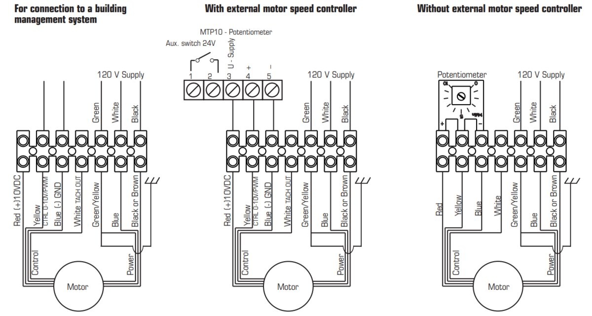
• Built-in potentiometer
The fan comes with a built-in 0-10V potentiometer that makes it easier to find the preferred working point without any additional wiring.
Typical applications for this model are supply or exhaust air duct systems in offices, day care facilities, schools, gymnasiums, crawl spaces, manufacturing facilities. Product can be configured with external devices that adjust airflow based on actual demand such as day/time schedule, occupancy, CO2 level, etc. The fan can also be used as a duct booster for extra-long duct runs in single-family homes.
The housing is manufactured from a two-piece stamped, galvanized construction. The two halves are joined using Fantech’s unique folded seam closure, which gives the fan the first in class, airtight seal.
The fan motors can operate in temperatures of air up to 140°F and the motor bearings are permanently sealed, self-lubricated for maintenance-free life. This model has built-in thermal overload protection with automatic reset needing no user intervention. With the motor in the airstream, the fan provides the constant dissipation of heat build-up thus giving the fan best in class for longevity and reliability. For the same air volume, this model consumes considerably less energy than an AC fan of its size.
The mounting bracket and hardware are included, the fan is ENERGY STAR® listed and comes with 5-year factory warranty.

| Nominal data | ||
|---|---|---|
| Voltage (nominal) | 120 | V |
| Frequency | 60 | Hz |
| Phases | 1~ | |
| Input power | 36 | W |
| Input current | 0.5 | A |
| Impeller speed | 4 087 | rpm |
| Air flow | max 82 | L/s |
| Temperature of transported air | -25 to 60 | °C |
| Max temperature of transported air, when speed controlled | 60 | °C |
| Protection/Classification | ||
|---|---|---|
| Enclosure class, motor | IP54 | |
| Insulation class | B | |
| Certificate | cULus |
| Dimensions and weights | ||
|---|---|---|
| Duct dimension; Circular, inlet | 4 | in. |
| Duct dimension; Circular, outlet | 4 | in. |
| Weight | 4.6 | lb |
| Optional | ||
|---|---|---|
| Duct connection type | Circular | |
| Motor type | EC | |
| Material | Metal |
HVI Certified Rating(s) |
||
Static Pressure (In. Wg.) |
Rated Airflow (CFM) |
Rated Power (Watts) |
0.20 |
160 |
36 |
| A | C | D | E | F | |
4XL EC |
4 (102) |
8 1/2 (216) |
6 1/2 (165) |
1 (25) |
1 (25) |
6M EC |
6 (152) |
13 1/8 (333) |
7 (178) |
1 (25) |
1 (25) |
8 EC |
8 (203) |
13 1/4 (337) |
6 (152) |
1 1/8 (29) |
1 (25) |
10 EC |
10 (254) |
13 1/4 (337) |
4 3/4 (121) |
1 1/8 (29) |
1 (25) |
12XL EC |
12 (305) |
16 (406) |
6 11/16 (170) |
1 1/2 (38) |
1 (25) |
Dimensions are in inches (mm). |
|||||

GUIDE SPECIFICATION
Specifier Notes: This guide specification is written in Construction Specifications Institute (CSI) 3-Part Format in accordance with The CSI Construction Specifications Practice Guide, MasterFormat, SectionFormat, and PageFormat.
Specifier Notes: This Section must be carefully reviewed and edited by the Architect or Engineer to meet the requirements of the Project and local building code. Coordinate this Section with Division 01, other specification sections, and the Drawings. Delete all Specifier Notes after editing this Section.
Section numbers and titles are based on MasterFormat 2014 Update.
SECTION 23 34 00
HVAC FANS
Specifier Notes: This Section covers Fantech FG EC / K EC Series circular inline duct fans with electronically commutated motors (ECM). Consult Fantech for assistance in editing this Section as required for the Project.
Specifier Notes: Use of FG EC / K EC Series circular inline duct fans may contribute to LEED credits.
PART 1. GENERAL
1.1 SECTION INCLUDES
A. Circular inline duct fans with EC (electronically commutated) motors
1.2 RELATED REQUIREMENTS
Specifier Notes: Edit the following list of related sections as required for the Project. Limit the list to sections with specific information that the reader might expect to find in this Section, but is specified elsewhere.
A. Section 23 31 00 – HVAC Ducts and Casings.
B. Section 26 05 00 – Common Work Results for Electrical.
1.3 REFERENCE STANDARDS
Specifier Notes: List reference standards used elsewhere in this Section, complete with designations and titles. Delete reference standards from the following list not used in the edited Section.
A. Air Movement and Control Association International (AMCA) (www.amca.org):
1. AMCA 211 – Certified Ratings Program - Product Rating Manual for Fan Air Performance.
2. HVI 916 – Listed and Tested Accordingly
1.4 PREINSTALLATION MEETINGS
Specifier Notes: Edit the Preinstallation Meetings article as required for the Project. Delete article if not required.
A. Convene preinstallation meeting [1 week] [2 weeks] before start of Work of this Section.
B. Require attendance of parties directly affecting Work of this Section, including Contractor, Architect, installer, and manufacturer’s representative.
C. Review the Following:
1. Materials
2. Installation
3. Adjusting
4. Protection
5. Coordination with other Work
1.5 SUBMITTALS
Specifier Notes: Edit the Submittals article as required for the Project. Delete submittals not required.
A. Comply with Division 01.
B. Product Data: Submit manufacturer’s product data, including installation instructions.
C. Shop Drawings: Submit manufacturer’s shop drawings, including plans, elevations, sections, and details.
1. Wiring Diagrams: Indicate wiring for each item of equipment and interconnections between items of equipment.
2. Include manufacturer’s names, model numbers, ratings, power requirements, equipment layout, device arrangement, complete wiring point-to-point diagrams, and conduit layouts.
D. Manufacturer’s Certification: Submit manufacturer’s certification that materials comply with specified requirements and are suitable for intended application.
E. Operation and Maintenance Data:
1. Submit manufacturer’s operation and maintenance manual; including the following:
a. Operation, maintenance, adjustment, and cleaning instructions.
b. Troubleshooting guide
c. Parts list
d. Electrical wiring diagrams if required.
2. Provide detailed information required for Owner to properly operate and maintain equipment.
F. Warranty Documentation: Submit manufacturer’s standard warranty.
1.6 QUALITY ASSURANCE
A. Manufacturer’s Qualifications: Manufacturer regularly engaged in the manufacturing of circular inline duct fans to that specified for a minimum of 10 years.
B. Installer's Qualifications:
1. Installer regularly engaged in installation of circular inline duct fans of similar type to that specified for a minimum of 5 years.
2. Use persons trained for installation of circular inline duct fans.
1.7 DELIVERY, STORAGE, AND HANDLING
A. Delivery Requirements: Deliver materials to site in manufacturer’s original, unopened containers and packaging, with labels clearly identifying product name and manufacturer.
B. Storage and Handling Requirements:
1. Store and handle materials in accordance with manufacturer’s instructions.
2. Keep materials in manufacturer’s original, unopened containers and packaging until installation.
3. Store materials in clean, dry area indoors.
4. Keep materials from freezing.
5. Protect materials during storage, handling, and installation to prevent damage.
1.8 WARRANTY
Warranty Period: 5 years
PART 2. PRODUCTS
2.1 MANUFACTURERS
A. Manufacturer: Fantech Inc., 10048 Industrial Blvd., Lenexa, Kansas 66215. Phone 800-747-6217. www.fantech.net. ussupport@fantech.net.
Specifier Notes: Specify if substitutions will be permitted.
B. Substitutions: [Not permitted] [Comply with Division 01].
C. Single Source: Provide materials from single manufacturer.
2.2 HVAC FANS
A. Circular inline Duct Fans with Electronically Commutated Motors (ECM): FG EC / K EC Series
1. Rating: AMCA 211
2. Compliance AMCA Certified Rating Programs
3. AMCA Air Seal
4. cULus Listed
5. ENERGY STAR® Rated
6. HVI 916
Specifier Notes: Specify circular inline duct fan models as required for the Project. Delete models not required.
B. Model: “FG 4XL EC / K 4XL EC”
1. Inlet Diameter: 4 inches
2. Outlet Diameter: 4 inches
3. Casing Diameter: 8-1/2 inches
4. Inlet and Outlet Connection Collars: 1 inch
5. Casing Material: Galvanized Metal with air-tight, folded seam construction. A housing seam joined with screws or rivets is unacceptable.
6. Motor: External-rotor ECM
7. Speed Control: Built-in potentiometer 0-10V
8. Motor Protection: electronically protected
9. Blades: Backward curved
10. Voltage: 120 V
11. Frequency: 50/60 Hz
12. Nominal Voltage Range: 100 to 130 V
13. Phase: 1
14. Maximum Airflow: 180 cfm
15. RPM: 4,038
16. Power Rating, Motor: 33 W
17. Current: 0.48 A
18. Operational Temperature: minus 13 to 140 degrees F
19. Weight: 4.6 lbs
20. Motor Insulation Class: B
21. Motor Enclosure Class: IP44
C. Model: “FG 6M EC / K 6M EC”
1. Inlet Diameter: 6 inches
2. Outlet Diameter: 6 inches
3. Casing Diameter: 13 1/8 inches
4. Inlet and Outlet Connection Collars: 1 inch
5. Casing Material: Galvanized Metal with air-tight, folded seam construction. A housing seam joined with screws or rivets is unacceptable.
6. Motor: External-rotor ECM
7. Speed Control: Built-in potentiometer 0-10V
8. Motor Protection: electronically protected
9. Blades: Backward curved
10. Voltage: 120 V
11. Frequency: 50/60 Hz
12. Nominal Voltage Range: 100 to 130 V
13. Phase: 1
14. Maximum Airflow: 364 cfm
15. RPM: 2,491
16. Power Rating, Motor: 74 W
17. Current: 1.0 A
18. Operational Temperature: minus 13 to 140 degrees F
19. Weight: 9 lbs
20. Motor Insulation Class: B
21. Motor Enclosure Class: IP44
D. Model: “FG 8 EC / K 8 EC”
1. Inlet Diameter: 8 inches
2. Outlet Diameter: 8 inches
3. Casing Diameter: 13 1/4 inches
4. Inlet and Outlet Connection Collars: 1 inch
5. Casing Material: Galvanized Metal with air-tight, folded seam construction. A housing seam joined with screws or rivets is unacceptable.
6. Motor: External-rotor ECM
7. Speed Control: Built-in potentiometer 0-10V
8. Motor Protection: electronically protected
9. Blades: Backward curved
10. Voltage: 120 V
11. Frequency: 50/60 Hz
12. Nominal Voltage Range: 100 to 130 V
13. Phase: 1
14. Maximum Airflow: 428 cfm
15. RPM: 2,515
16. Power Rating, Motor: 71 W
17. Current: 0.5 A
18. Operational Temperature: minus 13 to 140 degrees F
19. Weight: 8.4 lbs
20. Motor Insulation Class: B
21. Motor Enclosure Class: IP44
E. Model: “FG 10 EC / K 10 EC”
1. Inlet Diameter: 10 inches
2. Outlet Diameter: 10 inches
3. Casing Diameter: 13 1/4 inches
4. Inlet and Outlet Connection Collars: 1 inch
5. Casing Material: Galvanized Metal with air-tight, folded seam construction. A housing seam joined with screws or rivets is unacceptable
6. Motor: External-rotor ECM
7. Speed Control: Built-in potentiometer 0-10V
8. Motor Protection: electronically protected
9. Blades: Backward curved
10. Voltage: 120 V
11. Frequency: 50/60 Hz
12. Nominal Voltage Range: 100 to 130 V
13. Phase: 1
14. Maximum Airflow: 511 cfm
15. RPM: 2,311
16. Power Rating, Motor: 93 W
17. Current: 0.65 A
18. Operational Temperature: minus 13 to 140 degrees F
19. Weight: 9.2 lbs
20. Motor Insulation Class: B
21. Motor Enclosure Class: IP44
F. Model: “FG 12XL EC / K 12XL EC”
1. Inlet Diameter: 12 inches
2. Outlet Diameter: 12 inches
3. Casing Diameter: 16 inches
4. Inlet and Outlet Connection Collars: 1 inch
5. Casing Material: Galvanized Metal with air-tight, folded seam construction. A housing seam joined with screws or rivets is unacceptable.
6. Motor: External-rotor ECM
7. Speed Control: Built-in potentiometer 0-10V
8. Motor Protection: electronically protected
9. Blades: Backward curved
10. Voltage: 120 V
11. Frequency: 50/60 Hz
12. Nominal Voltage Range: 100 to 130 V
13. Phase: 1
14. Maximum Airflow: 807 cfm
15. RPM: 2,510
16. Power Rating, Motor: 166 W
17. Current: 1.16 A
18. Operational Temperature: minus 13 to 140 degrees F
19. Weight: 16 lbs
20. Motor Insulation Class: B
21. Motor Enclosure Class: IP44
2.3 ACCESSORIES
A. Silencers for Circular Ducts
Specifier Notes: Delete accessories not required.
1. Model: [“LD 4”] [“LD 6”] [“LD 8”] [“LD 10”] [“LD 12”]
2. Insulation Thickness: 2 inches.
B. Mounting Clamps for Circular Ducts
Specifier Notes: Delete accessories not required.
1. Model: [“FC 4”] [“FC 6”] [“FC 8”] [“FC 10”] [“FC 12”]
2. Material: Galvanized sheet metal with 1/3 inch neoprene lining
3. Width: 2-1/3 inches
4. Clamps Together: 2 screws
5. Quantity: 2 pcs per kit
C. External Remotely Mounted Potentiometer
Specifier Notes: Delete if not required.
1. Model: MTP10
2. Remotely mounted manual-speed control for air flow adjustments and balancing.
3. Voltage: 0 to 10V DC
4. Enclosure class: IP54
D. Demand controller for pressure and constant flow ventilation
Specifier Notes: Delete if not required.
1. Model: PCA1000 D2
2. The sensor control module for differential pressure and volume flow measures and indicates the pressure or, optionally, the volume flow in a ventilation system. The calculation of the volume flow is performed by entering the K-factor of the application.
3. Output Signal: 0 to 10V DC
4. Adjustable measuring range: 0 to 4 in.wg.
5. Enclosure class: IP54
PART 3. EXECUTION
3.1 EXAMINATION
A. Examine areas to receive circular inline duct fans.
B. Notify Architect of conditions that would adversely affect installation or subsequent use.
C. Do not begin installation until unacceptable conditions are corrected.
3.2 INSTALLATION
A. Install circular inline duct fans in accordance with manufacturer’s instructions at locations indicated on the drawings.
B. Attach duct work to inlet and outlet connection collars of circular inline duct fans in accordance with manufacturer’s instructions.
C. Electrical: Install electrical power to circular inline duct fans as specified in Section 26 05 00.
3.3 ADJUSTING
A. Adjust circular inline duct fans for proper operation in accordance with manufacturer’s instructions.
3.4 PROTECTION
A. Protect installed circular inline duct fans from damage during construction.
END OF SECTION


